Bullseye resonator
Design a single-photon source based on a quantum dot in a bullseye resonator
5/8/20245 min read
This tutorial is inspired by Ref. [1-3], where quantum dot is coupled to a bullseye resonator (also known as circular Bragg grating - CBG) to produce a source of single or entangled photons.
General considerations
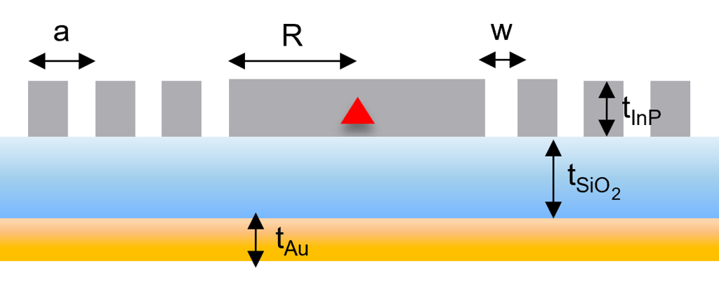
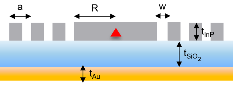
A bullseye resonator consists of a set of periodic concentric trenches etched in a semiconductor slab around a central disk, with QDs grown at half the slab thickness. The refractive index contrast at the trenches causes strong in-plane reflections, leading to a cavity resonance localized in the central disk. Meanwhile, part of the in-plane emission is directed vertically by the concentric rings which meet the second-order Bragg condition.
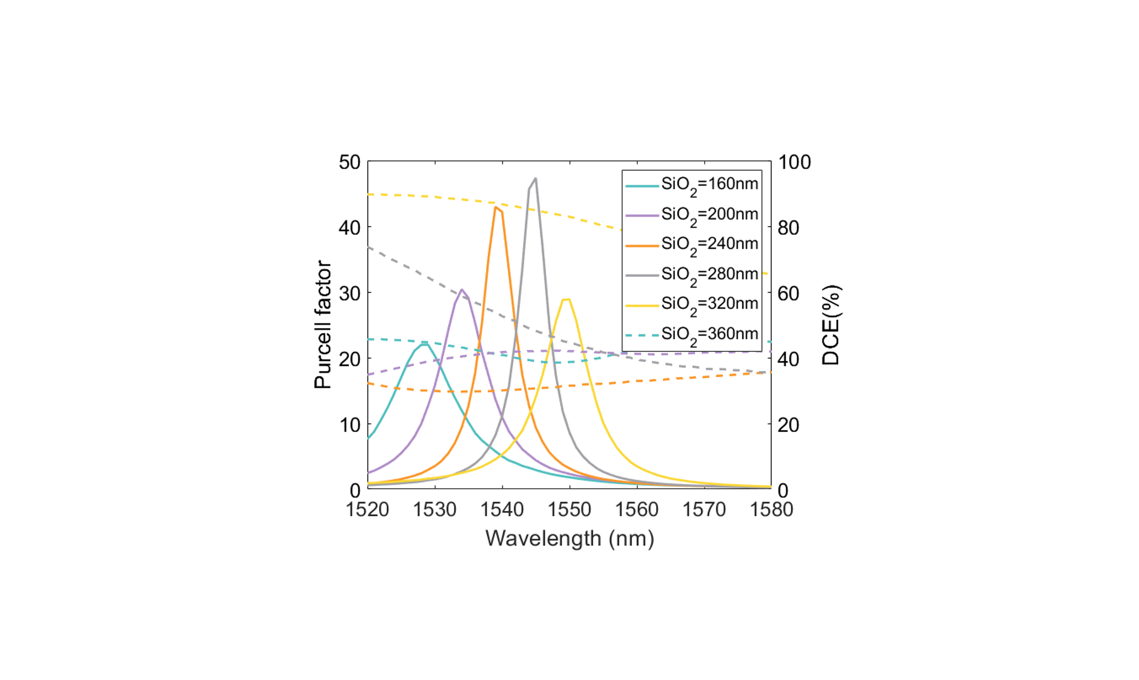
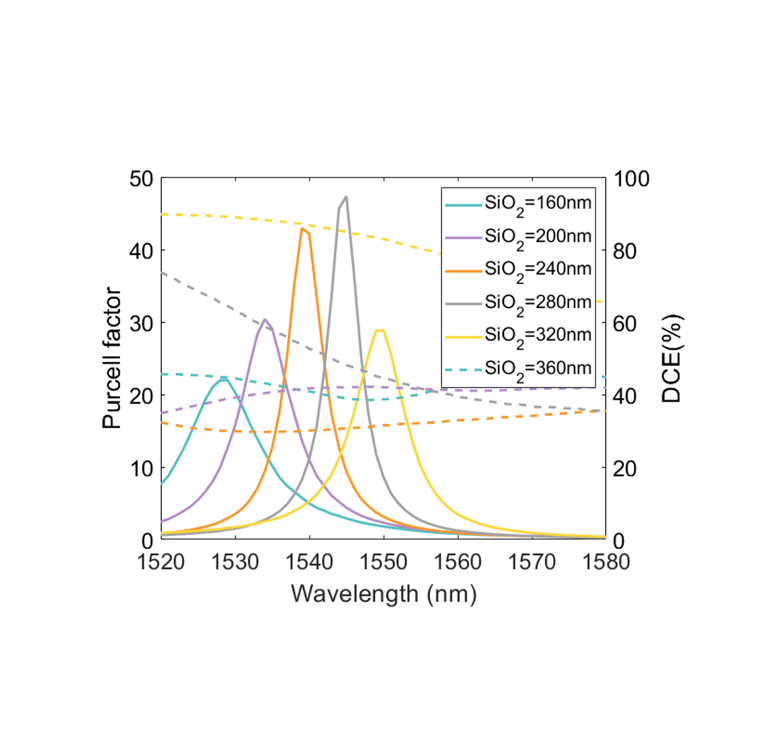
The device incorporates a backside broadband gold mirror, separated from the slab by an insulating SiO2 layer, to mitigate photon loss into the substrate. By optimizing the oxide thickness, photons that would otherwise be dispersed can be effectively reflected by the gold mirror and redirected upwards.
In this tutorial we consider an InP CBG for a single-photon source operating at λ=1550 nm. The key design parameters to be optimized include the thickness of the InP and SiO2 layers, the radius R of the central disk, the number N of concentric rings, the lattice constant (i.e. periodicity) of the grating a, and the width of the trenches w. The quantum dot emitter is modelled as a linear dipole, and the performance of the device is evaluated based on the Purcell factor (𝐹𝑝) and the collection efficiency within a given numerical aperture (NA). Since the linear dipole breaks the cylindrical symmetry of the bullseye resonator, the design process usually requires 3D FEM simulations to solve the wave equation in the frequency (or time) domain accurately.

Grating design (1D)
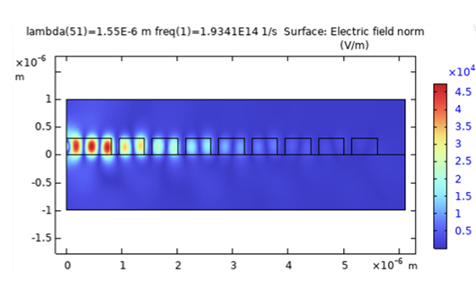
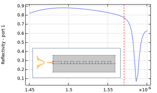
Given that solving a full 3D FEM model can be computationally intensive, an efficient starting point for the design process is to analyze a 1D InP grating, which corresponds to a radial cross-section of the bullseye resonator. This simplified model consists of an InP grating on a SiO₂ layer and immersed in air [1]. For a target resonance wavelength of λ = 1550 nm, initial design parameters can be set based on fundamental optical principles: the InP slab thickness is chosen as half the effective wavelength in InP to support only a single TE mode, the grating period is set to a = λ/ngrating to satisfy the second-order Bragg condition, and the trench width is taken as 50% of the lattice constant. The structure is excited by launching a 1D TE mode within the slab, and the reflectivity as a function of wavelength can be determined by monitoring the reflected power at the input port. The band edge of the reflection spectrum indicates the wavelengths at which photons will be reflected and partially scattered in the upward and downward directions. This can be further confirmed by visualizing the electric field distribution at the target wavelength. Since this 1D model is computationally efficient, it enables the exploration of a broad parameter space, facilitating the optimization of the grating design before transitioning to more complex 3D simulations.
Bullseye optimization (3D)
The optimized parameters from the 1D grating study serve as an initial guideline for refining the full 3D bullseye resonator design. In the 3D FEM model, perfectly matched layers (PMLs) are applied at the simulation boundaries to prevent artificial reflections and accurately represent open boundaries. An electric point dipole source, oriented along the y-axis, is positioned at the center of the structure (x = 0, y = 0) at half the slab thickness to emulate single-photon emission from a quantum dot [2].
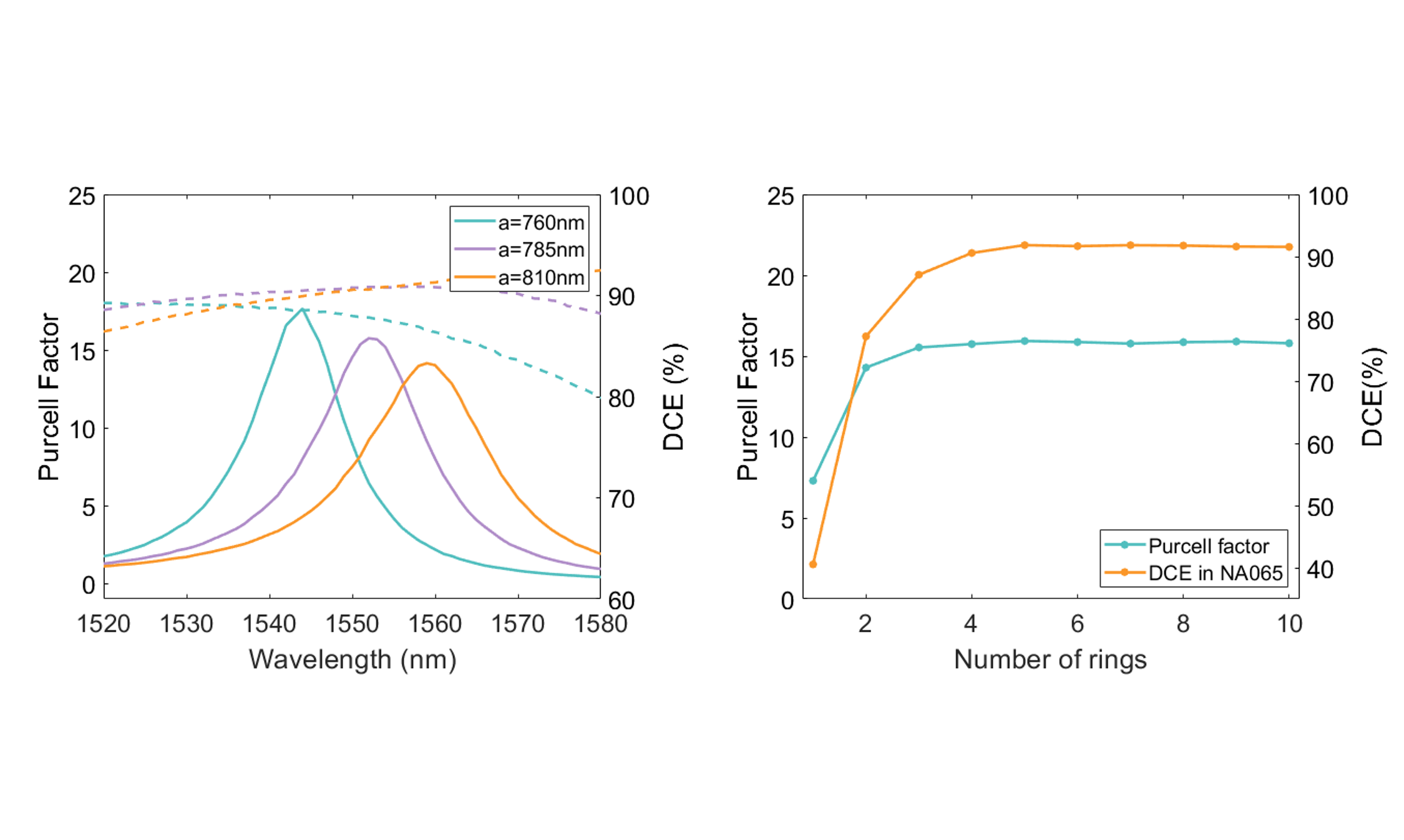
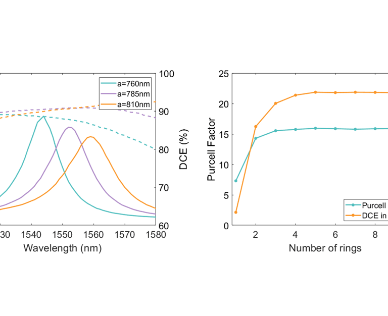
To evaluate the Purcell factor 𝐹𝑝, the power radiated by the dipole in the CBG is compared to that radiated in an infinite (or semi-infinite) InP environment. This is achieved by monitoring the power outflow through the simulation boundaries. The collection efficiency is assessed through three key metrics: the dipole extraction efficiency (DEE), defined as the fraction of emitted radiation that escapes into the air domain; the far-field efficiency (FFE), which quantifies the fraction of emitted light that falls within a specific numerical aperture (NA); and the dipole collection efficiency (DCE), given by the product of DEE and FFE. These metrics provide a comprehensive evaluation of the device’s ability to channel photons into a useful optical mode.
To optimize computational efficiency, symmetry considerations can be leveraged to reduce the size of the simulation domain. Specifically, by modeling only a quarter of the CBG structure and applying appropriate boundary conditions—perfect electric conductor (PEC) and perfect magnetic conductor (PMC)—one can effectively account for the full geometry. Additionally, to maintain a manageable computational load, it is advisable to begin with a simplified model containing a reduced number of concentric rings (e.g. N=4) before scaling up to the final design.
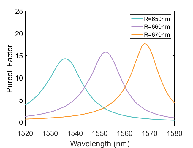
The resonance condition of the CBG cavity can be written as [4]:
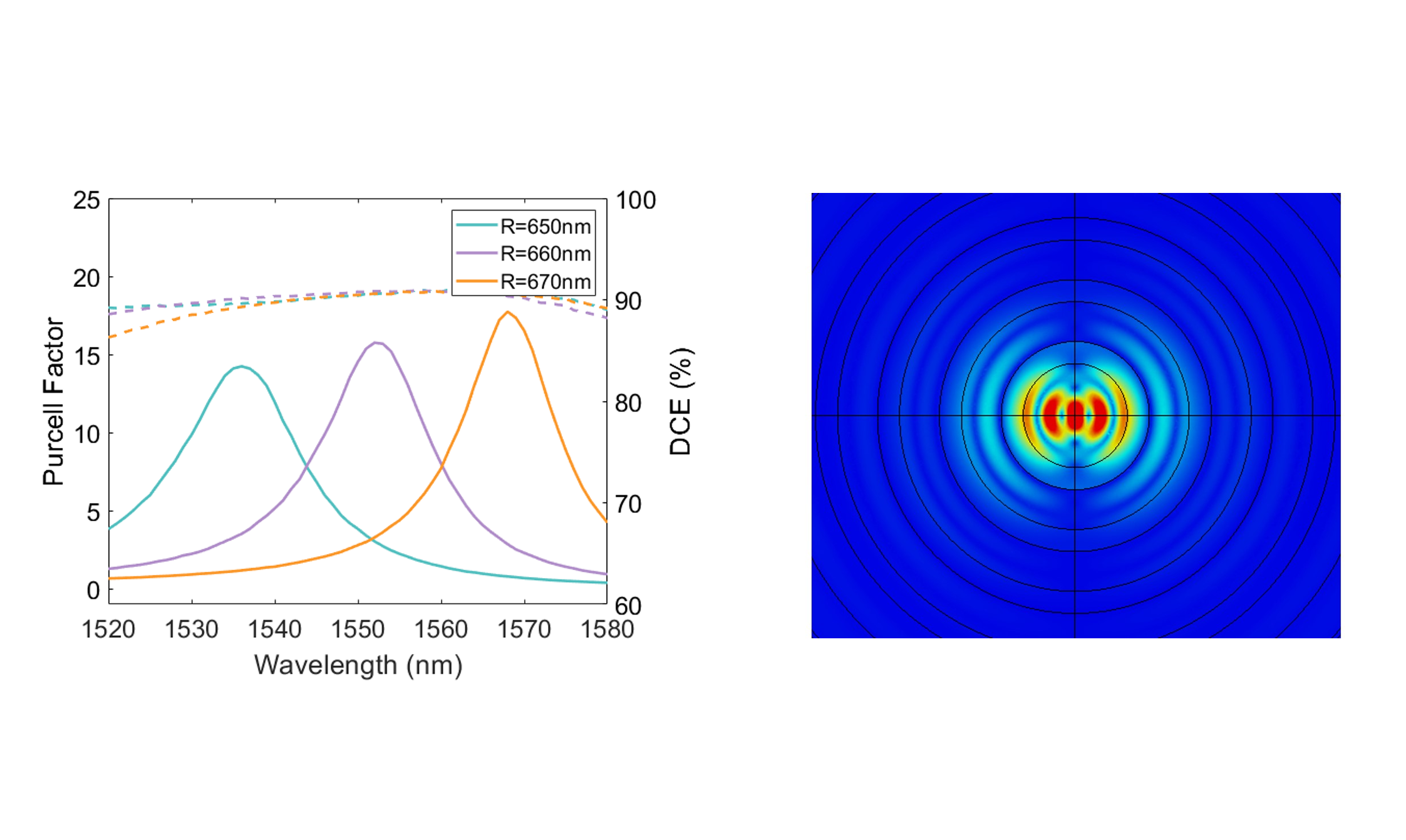
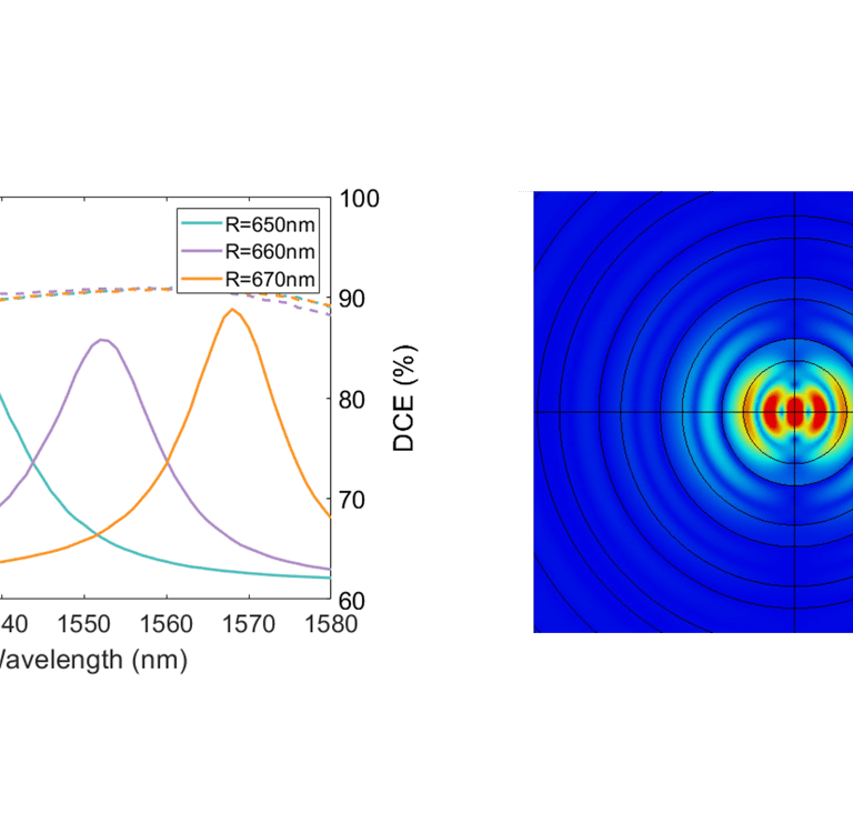
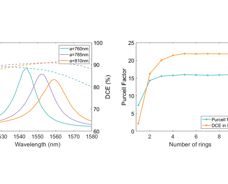
Once the optimal radius and oxide thickness are determined, further refinements can be made by adjusting the grating parameters to enhance both the Purcell factor and the collection efficiency. The trench width w, the grating period a, and the number of rings N influence the outcoupling efficiency. By varying these parameters and analyzing the corresponding figures of merit, an optimal balance can be achieved.
where leff is the penetration length of the mode into the grating. Therefore, the cavity resonance can be tuned to the desired wavelength by adjusting the radius R of the central disk. Again, it is important to verify the electric field profile and ensure that the optical mode remains well-confined within the central disk.
Finally, the impact of fabrication tolerances should be assessed to ensure that the design is robust against deviations in trench width and position of the quantum dot emitter. Sensitivity analyses, where key parameters are varied within realistic fabrication tolerances, can provide insights into the stability of the design
References
[1] Liu, J. et al., “A solid-state source of strongly entangled photon pairs with high brightness and indistinguishability” Nature Nanotechnology 14, 586–593 (2019).
[2] Rickert, L. et al., “Optimized designs for telecom-wavelength quantum light sources based on hybrid circular Bragg gratings” Optics express 27, 36824 (2019).
[3] Barbiero, A. et al., “Design study for an efficient semiconductor quantum light source operating in the telecom C-band based on an electrically driven circular Bragg grating” Optics express 30, 10919 (2022).
[4] Yao, B. et al., “Design for Hybrid Circular Bragg Gratings for a Highly Efficient Quantum-Dot Single-Photon Source” J. Korean Phys. Soc 73, 1502-1505 (2018).
Next, the backside Au mirror can be added to the model and the oxide thickness can be optimized with a simple parametric sweep. Depending on the application, one may choose the value that gives maximum Purcell factor or optimal DCE.