Coupling into fiber
Simulate the direct coupling of photons emitted by a quantum dot source into a single-mode fiber
TUTORIALS
3/7/20254 min read
For the development of compact and user-friendly light sources based on semiconductor quantum dots (QDs), direct fiber coupling of the emitted photons is highly desirable. Attaching an optical fiber directly to the semiconductor chip reduces system size and complexity while ensuring robust alignment outside the laboratory environment.
This tutorial is inspired by Refs. [1-2], which employ numerical simulations to investigate the light field emitted by a telecom QD and its coupling efficiency to an external optical fiber. In this case, the QD emitter is embedded in a bullseye resonator; however, the same approach can be applied to other photonic structures, such as microlenses [3] or micropillars [4]. Also, although this tutorial primarily refers to COMSOL Multiphysics, the approach and general considerations apply to other simulation platforms as well.
General considerations
Here, we consider a telecom QD emitting at λ = 1550 nm, embedded in a C-band InP bullseye resonator similar to the one presented in our previous tutorial. We assume that a single-mode (SM) fiber is positioned above the device at a distance z, perfectly aligned along the axial direction, with air (n = 1) filling the gap.
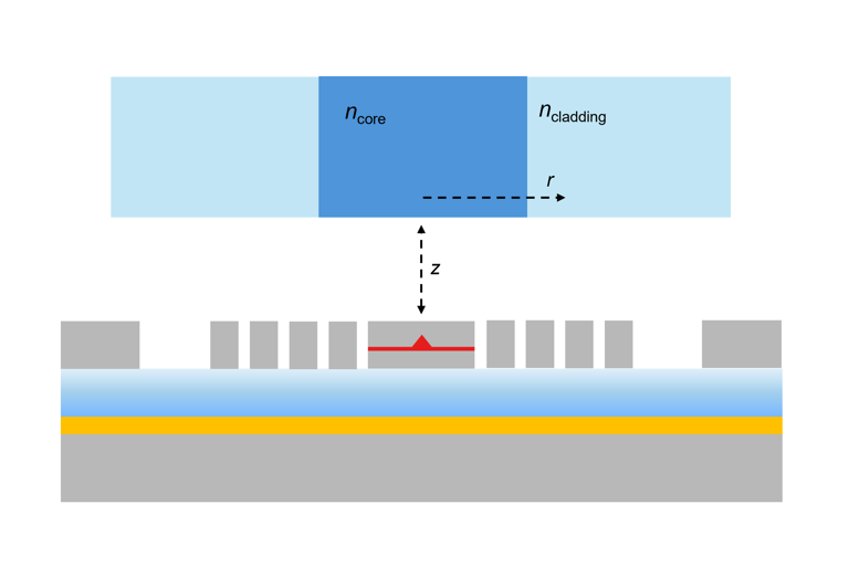
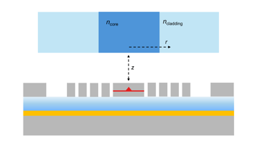
The coupling efficiency can be determined in three steps. First, we calculate the propagating modes supported by a specific fiber. Since these modes depend only on the fiber's characteristics, which remain invariant along the propagation direction, simulations can be performed on a 2D cross-section, reducing computational requirements. Next, we determine the profile of the scattered field Es emitted by a dipole source embedded in the bullseye resonator. Finally, we evaluate the overlap between the scattered field Es and the fundamental mode of the fibre Em. This overlap integral can be computed using the z-component of the Poynting vector [5]:
where the integration is performed over a cross-section of the fibre. The power flux coupled into the mode m is then given by:
and the mode coupling efficiency (MCE) can finally be extracted dividing Ps,m by the total power emitted by the dipole source.
It should be noted that this simple model of the field overlap does not yield accurate values of the coupling efficiency due to the complex profile of the near field pattern at the entrance of the fiber. However, it is a first approximation that could be used, for example, to study different commercial fibers and select the most promising one for a given nanophotonic structures.
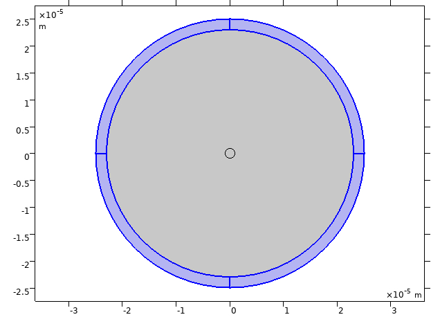
Single mode fiber (2D)
Since the optical fiber is invariant in the propagation direction, the simulation domain consists of a cross section, as shown in the figure below. The purple regions indicate perfectly matched layers (PMLs), which are used to set the boundary conditions.

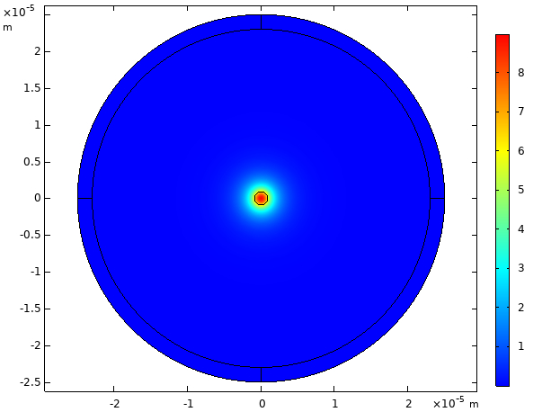
To calculate the propagating modes, Comsol Multiphysics provides a Mode Analysis study step, which is used to compute the propagation constants or wave numbers as well as propagating mode shapes for a given frequency. As an exemplary result, the figure below shows the electric field distribution calculated for the fundamental mode of an UHNA3 commercial fiber.

Scattered field and mode overlap
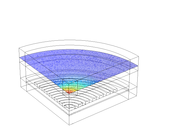
To calculate the field profile Es emitted by a dipole source embedded in the bullseye resonator, we use a 3D model similar to the one presented in this tutorial. The key difference here is the presence of an optical fiber near the device, which affects the emitted field profile and must therefore be included in the simulation. As demonstrated in [6], accurately determining the mode coupling efficiency (MCE) requires evaluating the scattered field tens of microns inside the fiber due to rather complex variation of the near field pattern upon distance from the surface. However, incorporating such a large portion of the fiber into the simulation domain would significantly increase computational costs. A practical alternative is to include only about 1 µm of fiber, accepting that this may overestimate the MCE. To further optimize computational efficiency, we impose appropriate boundary conditions to reduce the simulation domain to one-quarter of the full geometry, which decreases the required resources while maintaining accuracy. The figure below illustrates the norm of the scattered field evaluated at a distance of 500 nm from the fiber facet.

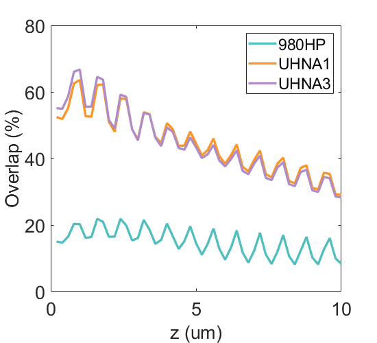
Finally, by calculating the overlap integral between the scattered field and the propagating modes, we can estimate the MCE as a function of the vertical distance z. The figure below shows the overlap calculated for four commercial SM fibers, which should then be multiplied by the extraction efficiency to extract the MCE. Although we stress that this approach overestimates the coupling efficiency, this calculation allows us to select the fibers with the best field profile matching - in this case, the three UHNA fibers - which provide the highest chance of achieving maximal coupling. As expected, the overlap decreases as a function of the distance z, due to beam divergence in the gap region. Additionally, all the curves exhibit moderate oscillations caused by Fabry-Perot interference between the chip surface and the fiber facet. [1].
References
[1] Rickert, L. et al., “Optimized designs for telecom-wavelength quantum light sources based on hybrid circular Bragg gratings” Optics express 27, 36824 (2019).
[2] Barbiero, A. et al., “Design study for an efficient semiconductor quantum light source operating in the telecom C-band based on an electrically driven circular Bragg grating” Optics express 30, 10919 (2022).
[3] Schneider, P. et al., “Numerical optimization of the extraction efficiency of a quantum-dot based single-photon emitter into a single-mode fiber” Optics Express 26, 8479–8492 (2018).
[4] Margaria N. et al., arXiv:2410.07760 (2024).
[5] https://www.jcmwave.com/docs
[6] Blokhin S. A. et al., “Design optimization for bright electrically-driven quantum dot single-photon sources emitting in telecom O-band” Optics Express 29, 6582–6598 (2021).